Showing posts with label helmet. Show all posts

Tuesday, August 31, 2010

Wrapping up the helmet

Day 12
Sunday.  Alex began sanding and prepping the plastic helmet for painting.  The Killer Chrome paint will be arriving on Monday.  We need to make the surface as shiny as possible or the paint will look horrible no matter how great the paint is.  For the most part, Sunday was pretty relaxed and not much happened.  I took the opportunity to work on my LED suit a bunch.

Day 13
Monday.  I began an all-out production line soldering up PCBs.  There are 16 boards that go behind the rainbow side colors, and two main jaw boards that house the PIC microcontroller, the equalizer, and the 3mm round chasers.  The rectangular boards with the three boards and the MOSFET are the rainbow boards.  You can't miss the big through-hole resistor added last-minute.  Oops.


Meanwhile, we tested the LEDs out with the colored cellophane, and we were not impressed at all.  The colors became very washed out under the bright LEDs.  We decided to make some white plastic diffusers that would double as a little structure for the thin colored material.  

Now for some bad news...

The Killer Chrome paint turned out to be a disaster, as we had worried might happen.  For some reason, even though the surface was smoothed and shiny at the start, no matter what we did, the jet black base coat always dried flat.  With a flat base coat, there was little hope for the chrome step.  As expected, from that point the chrome step didn't turn out well either, and it was all downhill from there.  Unfortunately, this is the one step we knew would cause us the most issues, and we were forced to resort to our backup plan:  plain old "chrome" spray paint.  

Day 14

Danny and I met up with Alex for our ritualistic lunch at Five Guys.  Alex pulled up and grabbed the gold spray-painted helmet out of the trunk and Danny and I both let out a sigh of relief.  It didn't look THAT bad.  Actually it still looked pretty awesome.  It's nowhere near Volpin-good, but its not bad.  

Alex designed the diffusers to snap right into the existing light frames.  Each one is a different shape and they are each numbered very secretively.  Sick!


Danny is starting to glue on some wires for the hair.  It looks like a very painful process.  After work, I started wiring up the electronics in the light frame assembly.  We convened at Alex's house around 8 PM to work on the final assembly.  I drilled and tapped the plastic frames to mount the PCBs with #4-40 screws, while Danny and Alex worked on the colored cellophane and the EKG decal.  The color material is doubled-up and glued with 3M spray adhesive.  


When both of our parts came together, we tested out the colors under the diffuser panels.  Pretty cool!  We mounted the light frames into the helmet.  


We adhered the visor to the helmet with some PSA (aka double-sided tape).  With some quick splicing of wires, we were able to get both sides running a test pattern.  We were expecting the two sides to slowly become out of sync, but happened sooner than we expected.  I will be adding some basic communication between the two sides in order to alleviate the sync issues.  We videotaped the "unveiling" since it was such a special moment.


All in all, I think we've done pretty good considering the circumstances.  We're way ahead of schedule, only a few small items remain.  Even though we knew we'd never reach perfection, we have learned a lot and it came out looking pretty nice.


Sunday, August 29, 2010

More Helmet - Vacuum forming & Circuitry

Day 10
Friday.  PCBs and components have arrived.  We've started the print job for the right half of the helmet, which should finish late Saturday evening.  I got the PCB parts from Danny and began soldering the components on.  Just trying to get the first LED to blink is turning out to be difficult.  Because we used the ExpressPCB el-cheapo Miniboard service, there are no silkscreens or solder masks.  Knowing where each component goes would have been nice, since Alex designed the boards and I'm doing the assembly.  But I'll just have to figure it out.

Also, a second smaller printer is printing the plastic frames that hold the LEDs behind the visor.  Here is a video of the smaller printer doing its thing:


Day 11 (Part 1)
Saturday afternoon.  Danny leaves for D*C in 5 days.  We test fitted one of the plastic light frames in the left helmet half.  The printer is still printing the other helmet half.  Alex has put about 6 or 7 coats of primer, spray paint, and wax on the MDF mold.  It has the finish of a bowling ball.  We wanted the finish to be perfect because we heard the plastic will pick up even the smallest of textures.  The vacuum former is complete with a hole in the side that is a perfect fit for the shop vac hose.  We cut our first piece of plastic to shape and mounted it between two frames of wood.  The plastic is clear PETG from McMaster.  With the mold looking so great, our expectations were set for success on our first try.

IMG_1191 IMG_1158 IMG_1155

Boy were we wrong. Our first mistake was trying it without the plastic being melted enough. Then the paint on the mold did not take the heat well and completely fused to the plastic. The resulting piece photographed below came from a lot of prying, cutting, and re-heating to get the mold out of the melted plastic. Notice the red paint all over the plastic.  FAIL.

IMG_1160

But after our first failure, we were determined to do it better.  And we did.  We decided to sand down the mold back to the first layer of primer.  We left the protective coating on the plastic this time as well, figuring it would help the mold release easier.  We also left our sheet of plastic a little larger to allow it to stretch around the steep sides more easily.  Here is a video of our second attempt:


Success!  We were all amazed at how incredibly well it worked this time.  We sketched the sharpie line on the formed plastic and with a little prying the mold came out. Using some shears we cut the piece to the rough shape. Using the first bad mold as a tray, Alex hit the inside of the good part with some spray tint from the auto parts store.
IMG_1162 IMG_1167 IMG_1170

 A few minutes later we test fitted it on the helmet half. And to wrap things up, we honed our vacuum forming skills making a few more copies as backups in case the tinting or trimming was difficult.  At this point, things are turning out WAY better than we had hoped.  Our first vacuum forming experience ever turned out to be an amazing success!

IMG_1173 IMG_1175 IMG_1197

Day 11 (Part 2)
Saturday Evening.  Checking up on the printer, it looks like the right side is almost done.  Check out the video to see how the printer can print some overhangs without any support underneath if the angle is right.


IMG_1203 IMG_1202


While that finished up, I tried to figure out why the PCBs weren't working properly.  It turned out that while rushing to finish the design, we completely overlooked the fact that the darlington transistor arrays we chose to power the LEDs are N-channel, meaning they sink current.  We had them hooked up as if they were sourcing current.  Essentially that meant both leads of each LED were connected to ground, so nothing was going to light up.  With some "slight" modifications to the PCB, I was able to cut some bad traces with an exacto knife and solder wires to the right locations.  Voila, we have light!  I wrote up a quick test pattern to make sure the shift registers were working.


IMG_1204

We tested the LEDs under the plastic frames.  Danny has the colored material at his house, but a paper towel will suffice for now.  At 2AM, that pretty much concludes our Saturday night.  And even though the right side of the helmet looks exactly like the left side, it is so pretty I have to post it.


IMG_1206

But wait, there is more progress!  Click here to see Part 3.

Thursday, August 26, 2010

The Beginnings of the Helmet

After seeing Volpin's video "How to make a Daft Punk Helmet in 17 Months", my friend Danny decided he wanted to make one of his own.  Soon the talk turned into action after his brother Alex started modeling the helmet in Solidworks for fun.  The helmet turned into an obsession and soon we had a very accurate 3D model that was actually manufacturable.  Danny was quickly convinced that we could actually pull off some sort of Daft Punk helmet for Dragon*Con 2010 this year.  All of us were extremely impressed with Volpin's craftsmanship and attention to detail.  But 17 months is a long time.  We thought it would be interesting to see if we could pull it off in 17 days (with the help of some sophisticated tools).

Days 1-3:  Solid Models

Render2 Render1 Render3 Iso view, no visor

Day 4:  
The true number of man-hours Alex spent on the solid model is unknown, but Saturday, August 21st is when all the action started.  We hardly had to lift a finger (literally).  With a little help from modern technology, we pressed the "print" button and the helmet started taking shape.  To make the complex shape of the helmet, we are using an FDM printer.  FDM (or fused deposition modeling) is a process where melted plastic (polycarbonate in this case) is fed through a print head and stacked up layer by layer to make real 3D parts out of plastic.  Over 24 hours is required to print one half alone, but the results were very impressive.

Day 5:
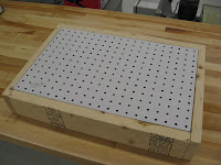
Sunday.  As the printer continued to do its thing, there were plenty of other items to take care of.  Danny got to work making a vacuum former for the visor.  The base is a couple of 2x4's and some perf-board from Home Depot.  We had planned to make a mold for the visor out of 3/4" MDF layers stacked and glued together.  The whole block would then be CNC milled to shape.  We blindly started milling the block on a ProtoTrak CNC bridgeport-style mill.  After making a large mess of sawdust, we found out we didn't have enough Z-travel to make the entire mold without pulling some tricks in CAM software.  The results were good, but we needed a better solution.

  Visor mold on ProtoTrak CNC mill 

Day 6:
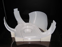
Monday.  The left half of the helmet is finished printing, along with the backer plate for the hair.  The printer adds support material under overhangs or empty spaces, and the support is broken off by hand.  Here you you can see Danny test fitting the helmet half with some support remaining in the ear area.


Day 7:
Tuesday.  Work continued on the side tasks, primarily finishing some design details with the plastic frames to hold the LEDs and the PCB design.  In the interest of time, we decided to make the PCBs using the dreaded ExpressPCB software.  While the software is a little outdated and clunky, they do get the job done fast and cheap.  Danny also got to ordering the materials for the visor and LED covers.  Below is the final layout for the PCB.

PCB-Screenshot

Day 8
Wednesday.  Danny and Alex come up with a new plan for the visor mold, involving a much bigger CNC mill. Below is a picture of Alex and his CNC (taken during another project), along with pictures (and video!) of the visor mold being machined.  First a roughing pass was made with a 1" endmill taking 1" steps.   Then another roughing pass was made with an extra-long 1/2" ball endmill and then a finishing pass.


The result is a work of art (and a giant mess).  You can even see the indentation that Alex left in the solid model so we would know where the visor needed to be cut after the sheet of plastic is formed over it.


Day 9
Thursday.  Work continues.  The PCB design was finalized and order was placed with rush delivery so we could have them over the weekend.  Coats of primer were added to the mold, along with more sanding to get the smoothest finish possible.


That brings us up to where we stand today.  Still lots of work ahead.  I've learned that writing a blog takes a lot of time too!  Hopefully I can make regular posts with progress.  For tonight, it's time for me to move on to my other projects!

There has been more progress on this project:  See Part 2 Here.